


How can the reliability of the grounding system be ensured during the fabrication of an electric control cabinet to prevent the risk of electric shock?
Release Time : 2026-01-15
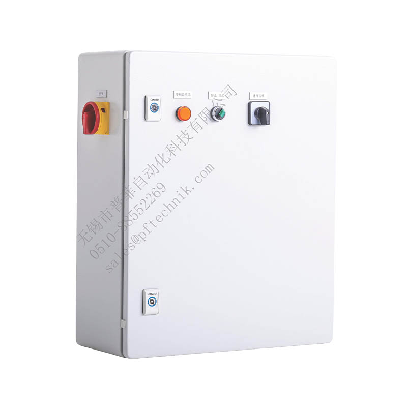
As a core component of industrial automation systems, the reliability of the grounding system in electric control cabinets directly affects the safe operation of equipment and the personal safety of operators. During manufacturing, a systematic protection system must be constructed, encompassing material selection, structural design, installation techniques, and testing and maintenance, to eliminate the risk of electric shock. The following outlines specific measures to ensure the reliability of the grounding system from seven key dimensions.
The core materials of the grounding system must meet both conductivity and durability standards. Copper should be the preferred material for the grounding conductor, as it has superior conductivity compared to aluminum, stronger corrosion resistance, and can maintain stable low resistance characteristics over a long period. The cross-sectional area of the grounding busbar must be determined comprehensively based on the equipment's load current and fault current capacity to ensure it will not melt due to overheating under extreme operating conditions. The metal frame of the cabinet should be made of galvanized steel or stainless steel to prevent grounding continuity interruptions due to corrosion. Connecting bolts should be made of stainless steel and equipped with anti-loosening spring washers to prevent loosening due to vibration.
The structural design of the grounding system must adhere to the principle of equipotential bonding. All metal components within the electric control cabinet, including the casing, mounting plates, guide rails, and cable trays, must be electrically connected to the grounding busbar via highly conductive connectors. For drawer-type or modular electric control cabinets, each independent unit must have a dedicated grounding terminal connected to the main grounding busbar via a flexible conductive strip to ensure uninterrupted grounding during insertion and removal operations. The shielding layer of shielded cables should use a single-end grounding method, reliably connected to the PE busbar on the electric control cabinet side via grounding clamps to avoid ground loop interference.
Standardized installation procedures are crucial for ensuring grounding reliability. The grounding busbar should be installed vertically along the bottom of the cabinet, with a sufficient number of grounding bolt holes for easy grounding of equipment within the cabinet. For painted mounting plates, the paint layer must be removed at the grounding point, or a toothed washer should be used to break the paint film to ensure that the electrical contact resistance between the electrical equipment and the mounting plate meets standard requirements. Grounding wires should use yellow-green insulated conductors, and their cross-sectional area must be selected according to the load type: the cross-sectional area of the grounding wire for single-phase loads should match that of the phase wire; the cross-sectional area of the neutral point grounding wire for the secondary winding of the current transformer should not be less than 2.5 mm²; and the grounding wire for surge protectors must meet the cross-sectional area requirements specified by the equipment manufacturer.
Electromagnetic compatibility design must be deeply integrated with the grounding system. For high-interference equipment such as frequency converters and servo drives, independent grounding bars must be used and connected to the main grounding busbar through short, thick conductors to reduce high-frequency noise interference to the control system. The shielding layer of shielded cables should be grounded at one end on the electric control cabinet side, and the grounding point should be as close as possible to the equipment entrance. For control systems requiring cross-area wiring, equipotential grounding terminals must be installed in each junction box, and a continuous grounding network must be formed through the grounding trunk line to prevent electric shock accidents caused by potential differences.
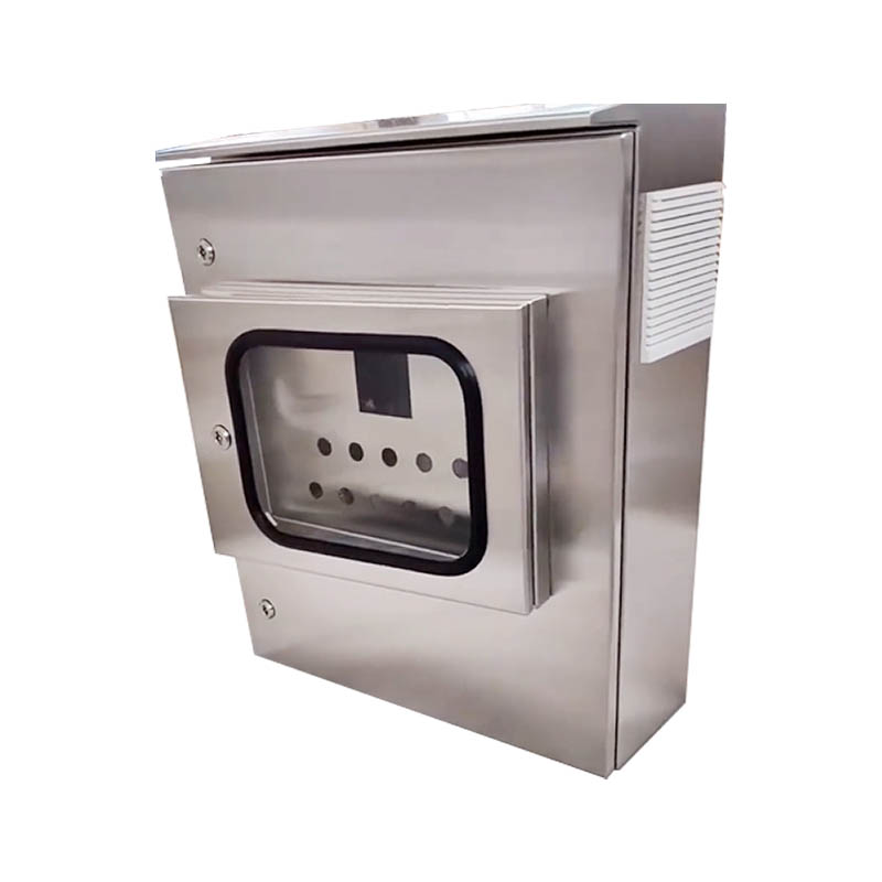
Safety protection measures must be implemented throughout the entire manufacturing process. Openable components such as the electric control cabinet door and instrument doors must be flexibly connected to the cabinet frame using braided copper strips to ensure that grounding continuity is not affected during frequent opening and closing. For outdoor-installed electric control cabinets, rain covers must be installed at the grounding terminals to prevent rainwater intrusion and increased grounding resistance. Conductive grease or a conductive coating must be applied or sprayed at the connection between the grounding busbar and the cabinet to reduce contact resistance and prevent oxidation and corrosion. For control systems requiring artificial grounding, a clearly visible grounding marker must be installed on the exterior of the cabinet, and dedicated grounding bolts must be provided for easy on-site installation and testing.
Inspection and maintenance mechanisms are crucial for ensuring the long-term reliability of the grounding system. Before the electric control cabinet leaves the factory, a low-resistance tester must be used to comprehensively test the grounding circuit to ensure that the resistance value between the cabinet and the grounding electrode meets standard requirements. For electric control cabinets already in operation, a regular inspection system must be established, focusing on checking for loose grounding wire connections, corrosion of the grounding busbar, and clarity of grounding markings. During rainy seasons or in humid environments, the frequency of inspections should be increased, and grounding resistance should be dynamically monitored. For any problems discovered, immediate corrective measures such as tightening connections, replacing wires, and applying anti-corrosion treatment must be taken to ensure the grounding system is always in good condition.
Standardized management is the fundamental guarantee for improving the reliability of the grounding system. During the design phase of the electric control cabinet, grounding system drawings must be prepared in strict accordance with electrical safety standards, clearly defining the grounding methods and connection requirements for each component. During manufacturing, comprehensive process documentation and inspection specifications must be established, with quantitative control over key parameters such as the cross-sectional area of the grounding conductor, the torque of connecting bolts, and the limits of grounding resistance. For mass-produced electric control cabinets, a first-article inspection and in-process sampling inspection system must be implemented to ensure that the grounding system of each product meets design requirements. By constructing a standardized management system covering the entire lifecycle, design defects and manufacturing flaws in the grounding system can be fundamentally eliminated, providing a solid guarantee for the safe operation of industrial automation systems.